This circuit is not my idea but has been taken from CD32 design. By the way, that's pretty strange why this never went into regular production for the other models? At the bottom of window you can see a piece of the CD32 mainboard enclosed in the metal case - this has been built for A500 as the standalone PAL encoder. OverviewActually, there are three phases to achieve finally composite signal.
1. RGB >> YUV. 2. YUV >> YC. 3. YC >> Composite. If the
last phase known as YC mix process will omit a black and white
information which is most responsible for quality will have "more space"
in a separate wire. This is because PAL/NTSC systems have limited video
bandwidth to about 4-6MHz and if a B&W info (commonly referred as
lumination or Y) is mix together with a coded color info (commonly referred as
chromination or C) then they must share the bandwidth and in the effect
there are some visible degradations on the final picture. 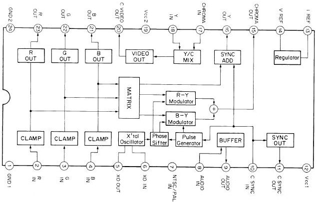
There's one more interesting thing about CXA1145 - It has RGB outs. A few additional discrete parts can be video sources at the same time as all the others outputs. However, in A1200/A600 it's sensless because of the direct RGB output stage from DACs. 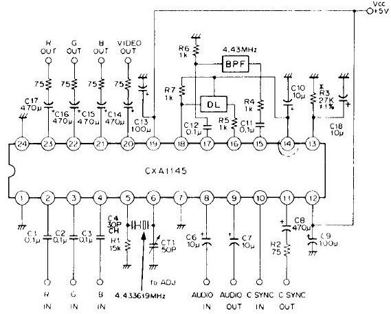 Principles
ImplementationFor the best results all parts should be smd. The 75ohm resistors (1%
metal-film are recommended) should be located as close as possible to the
capacitors to minimize noise pickup and reflections caused by impedance
mismatch. The 100uF capacitor should be a tantalum type or a low
inductance electrolytic type for good and stable frequency response as well
the 1nF cap should be a ceramic smd rather than any other type.
S-video socket should be connected by the 75ohm wires and the traces
between bases T1, T2 and the CXA1145 pins should be kept as short as
possible for maximum performance. 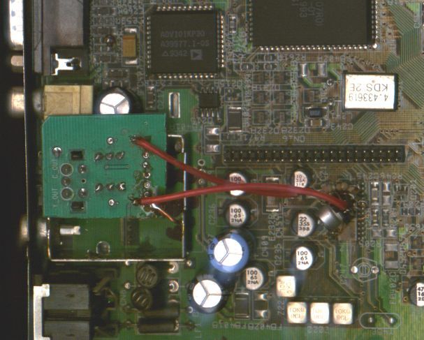 This is the schematic.
  Here are the video frames captured and saved with lossless compresion for objective compare from both Composite and S-Video outputs. The differences can be easily visible because quality of sharpness and color reproduction is somewhat different. These frame grabs were taken from A500 and the standalone PAL encoder, so.. this is not the best result, especially when encoder wasn't made with the highest quality parts... Unfortunately, my old A1200 have damage sync line and this is all I could put on this page. Composite B&W: visible loss of luma bandwidth (horizontal resolution), there's less details and the subsequent loss of sharpness S-Video B&W:  Composite color: here's very nice noticeable cross-color interference and color ringing caused by crosstalks from mixed Y-C bands  S-Video color:  Standalone PAL encoder 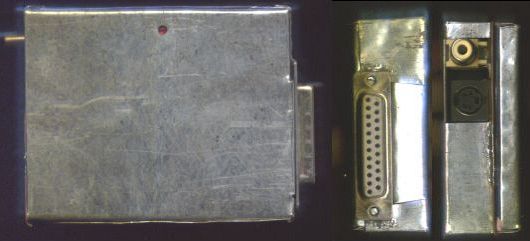
| |||||||||