Chapter 2. Using the GNU Tools
- Table of Contents
- 2.1. The Project
- 2.2. Compiling and Linking
- 2.3. "Map" Files
- 2.4. Generating .hex Files
- 2.5. Letting Make Build the Project
At this point, you should have the GNU tools configured, built, and installed on your system. In this chapter, we present a simple example of using the GNU tools in an AVR project. After reading this chapter, you should have a better feel as to how the tools are used and how a Makefile can be configured.
2.1. The Project
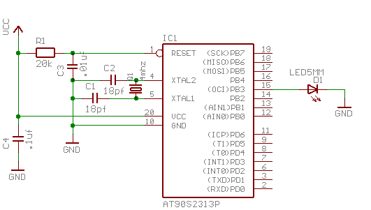
This project will use the pulse-width modulator (PWM) to ramp an LED on and off every two seconds. An AT90S2313 processor will be used as the controller. The circuit for this demonstration is shown in Figure 2-1. If you have a development kit, you should be able to use it, rather than build the circuit, for this project.
The source code is given in Example 2-1. For the sake of this example, create a file called demo.c containing this source code. Some of the more important parts are:

- The PWM is being used in 10-bit mode, so we need a 16-bit variable to remember the current value.

- SIGNAL() is a macro that marks the function as an interrupt routine. In this case, the function will get called when the timer overflows. Setting up interrupts is explained in greater detail in Chapter 6.

- This section determines the new value of the PWM.

- Here's where the newly computed value is loaded into the PWM regsiter. Since we are in an interrupt routine, it is safe to use outw(). Outside of an interrupt, outw_atomic() should be used.

- This routine gets called after a reset. It initializes the PWM and enables interrupts.

- The main loop of the program does nothing -- all the work is done by the interrupt routine! If this was a real product, we'd probably put a sleep instruction in this loop to conserve power.
Example 2-1. Demo source code
    /*
     * ----------------------------------------------------------------------------
     * "THE BEER-WARE LICENSE" (Revision 42):
     * <joerg@FreeBSD.ORG> wrote this file.  As long as you retain this notice you
     * can do whatever you want with this stuff. If we meet some day, and you think
     * this stuff is worth it, you can buy me a beer in return.        Joerg Wunsch
     * ----------------------------------------------------------------------------
     *
     * Simple AVR demonstration.  Controls a LED that can be directly
     * connected from OC1/OC1A to GND.  The brightness of the LED is
     * controlled with the PWM.  After each period of the PWM, the PWM
     * value is either incremented or decremented, that's all.
     *
     * $Id: simple-demo.c,v 1.3 2002/02/11 19:51:51 j Exp $
     */

    #include <io.h>
    #include <interrupt.h>
    #include <sig-avr.h>

    #if defined(__AVR_AT90S2313__)
    # define OC1 PB3
    # define OCR OCR1L
    # define DDROC DDRB
    #elif defined(__AVR_AT90S2333__) || defined(__AVR_AT90S4433__)
    # define OC1 PB1
    # define DDROC DDRB
    # define OCR OCR1L
    #elif defined(__AVR_AT90S4414__) || defined(__AVR_AT90S8515__) || \
    	defined(__AVR_AT90S4434__) || defined(__AVR_AT90S8535__) || \
    	defined(__AVR_ATmega163__)
    # define OC1 PD5
    # define DDROC DDRD
    # define OCR OCR1AL
    #else
    # error "Don't know what kind of MCU you are compiling for"
    #endif

    volatile uint16_t pwm;
    volatile enum
    {
      UP, DOWN
    }
    direction;


    SIGNAL(SIG_OVERFLOW1)
    {

      switch (direction)
        {
        case UP:
          if (++pwm == 1023)
    	direction = DOWN;
          break;

        case DOWN:
          if (--pwm == 0)
    	direction = UP;
          break;
        }

      __outw(pwm, OCR);
    }

    void
    ioinit(void)
    {

    #if defined(COM11)
      outp(BV(PWM10)|BV(PWM11)|BV(COM11), TCCR1A); /* tmr1 is 10-bit PWM */
    #elif defined(COM1A1)
      outp(BV(PWM10)|BV(PWM11)|BV(COM1A1), TCCR1A); /* tmr1 is 10-bit PWM */
    #else
    # error "need either COM1A1 or COM11"
    #endif
      outp(BV(CS10), TCCR1B);	/* tmr1 running on full MCU clock */

      __outw(0, OCR);		/* set PWM value to 0 */

      outp(BV(OC1), DDROC);		/* enable OC1 and PB2 as output */

      timer_enable_int(BV(TOIE1));
      sei();			/* enable interrupts */

    }

    void
    main(void)
    {

      ioinit();

      for (;;)
        /* wait forever, the interrupts are doing the rest */;
    }